
In the world of software development, UML diagrams are like the secret sauce that makes everything taste better. They’re not just fancy pictures; they’re powerful tools that help teams visualize complex systems and communicate ideas clearly. If you’ve ever tried to explain a project without a diagram, you know it can feel like herding cats—chaotic and a bit messy.
From class diagrams to sequence diagrams, each type serves a unique purpose, making it easier to understand the big picture. Whether you’re a seasoned developer or just dipping your toes into the tech pool, mastering these diagram types can elevate your projects from “meh” to “wow!” So buckle up and get ready to dive into the colorful world of UML diagrams—where clarity meets creativity and confusion takes a backseat.
Overview of UML Diagram Types
UML diagrams encompass various types, each tailored to different aspects of software design. Class diagrams illustrate the structure of a system by showcasing classes, attributes, and relationships. Behavioral diagrams detail system interactions, while structural diagrams emphasize system organization.
Sequence diagrams represent the flow of messages between objects, emphasizing time sequences. Use case diagrams display system functionality from a user’s perspective, identifying interactions and requirements. Interaction overview diagrams offer a high-level view of how different interactions occur within the system.
Activity diagrams model dynamic aspects, depicting workflows and process structures. Component diagrams visualize the parts of a system in terms of components and their interfaces. Deployment diagrams illustrate the physical deployment of artifacts, helping teams understand runtime configurations.
State machine diagrams represent the states of an object throughout its life cycle, providing insights into behavior changes triggered by events. Timing diagrams express how time constraints affect interactions within a system, emphasizing the time-dependent aspects of behavior.
To utilize UML diagrams effectively, developers must choose appropriate types based on project needs. Each diagram type plays a crucial role in enhancing communication and providing clarity throughout the software development process. Understanding these diagram types fosters better collaboration among team members and leads to more successful project outcomes.
Structural UML Diagram Types
Structural UML diagrams focus on the organization of system components, showcasing how different elements relate to each other. These diagrams provide essential insights for developers, enhancing system architecture understanding.
Class Diagram
Class diagrams illustrate the design of a system by representing classes and their relationships. Each class shows attributes and methods, forming the foundation of the object-oriented design. Associations, inheritance, and dependencies are clearly depicted, enabling developers to visualize system interactions. For example, a class diagram might represent a “Customer” class that relates to “Order” and “Payment” classes, elucidating the system’s structural relationships.
Component Diagram
Component diagrams present an overview of the physical components in a system. Each component serves a specific role, defining the structure at a higher level than class diagrams. Interactions among components are shown, including interfaces and dependencies. For instance, a component diagram could represent a web application with components like “User Interface,” “API,” and “Database,” detailing how they cooperate to form a complete system.
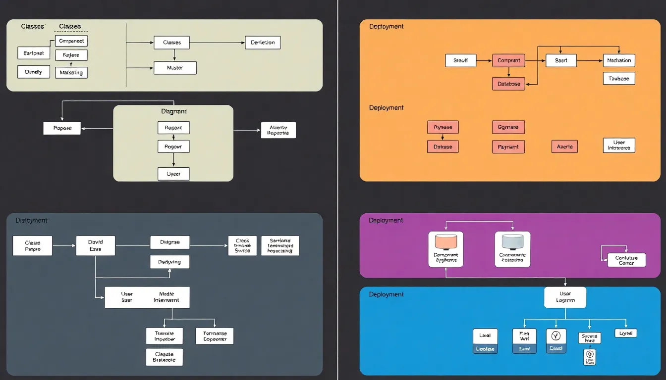
Deployment Diagram
Deployment diagrams illustrate the physical deployment of software artifacts on hardware nodes. Each node represents a physical device, while artifacts denote the software used on these devices. This diagram aids in understanding runtime environments and their configurations. A deployment diagram may feature a server hosting a web application linked to various client devices, providing clarity on how users interact with the system in real-time.
Behavioral UML Diagram Types
Behavioral UML diagrams focus on the dynamic aspects of a system, illustrating the interactions and behavior of system components. These diagrams include use case, sequence, and activity diagrams, each serving a unique purpose in understanding system functionalities.
Use Case Diagram
Use case diagrams represent external interactions between users and the system. Each diagram highlights the system’s functionality from a user’s perspective, detailing the various ways users can engage with system features. Actors, such as users or other systems, interact with use cases, signifying specific goals. For instance, an online shopping application may show actors like “Customer” and “Admin,” with use cases including “Browse Products,” “Place Order,” and “Manage Inventory.” This visualization aids in identifying requirements and clarifying system boundaries.
Sequence Diagram
Sequence diagrams illustrate how objects interact in a time-ordered sequence. They emphasize the flow of messages exchanged between various components during particular processes. Each object, represented as a vertical line, interacts with others through horizontal arrows indicating messages. In a banking system, a sequence diagram could show how a “Client” object sends a request to an “ATM” object, which in turn communicates with a “Bank Server” object to process a transaction. This representation helps developers understand object interactions and the temporal aspect of processes.
Activity Diagram
Activity diagrams model the workflow and activities within a system. Each diagram showcases the sequence of actions and decisions taken during a process, providing a clear visualization of parallel and conditional flows. Activities represent tasks, while diamonds indicate decision points that lead to multiple outcomes. In a project management tool, an activity diagram might illustrate steps like “Start Project,” “Assign Tasks,” and decision points like “Task Completed?” This structure clarifies operations, aiding teams in identifying bottlenecks and optimizing workflows.
Interaction UML Diagram Types
Interaction UML diagrams depict the communication between system components. They illustrate how these entities engage and exchange information, providing valuable insights into system behavior.
Communication Diagram
Communication diagrams highlight the relationships between objects and the messages they exchange. These diagrams present a visual representation of interactions, focusing on the collaboration aspect. For instance, in an online banking system, a communication diagram may illustrate the interaction among a “User,” “Account,” and “Transaction” objects. Each message is labeled, indicating the specific action taken, such as “Request Balance” or “Initiate Transfer.” Additionally, they maintain a focus on organizing these interactions in a way that emphasizes the overall structure of the system’s communication network.
Timing Diagram
Timing diagrams offer a detailed view of how interactions occur over time. They represent the time constraints of messages and events between objects within a scenario. In an automated car control system, a timing diagram might display the relationship between “Speed Sensor,” “Braking System,” and “Controller” to demonstrate how signal timing affects system response. Events are timestamped, showing the exact duration between actions like “Accelerate” and “Decelerate.” This diagram type assists in understanding real-time behaviors, particularly in scenarios where timing is critical for functionality and performance.
UML diagrams play a crucial role in software development by providing clarity and enhancing communication. Mastering the various types of UML diagrams equips developers with the tools needed to visualize complex systems effectively. Each diagram type serves its unique purpose, whether illustrating structure, behavior, or interactions.
By incorporating these diagrams into their workflow, teams can streamline processes and foster collaboration. This understanding not only improves project outcomes but also empowers developers to tackle challenges with confidence. Embracing UML diagrams is a step toward achieving greater efficiency and creativity in software design.